
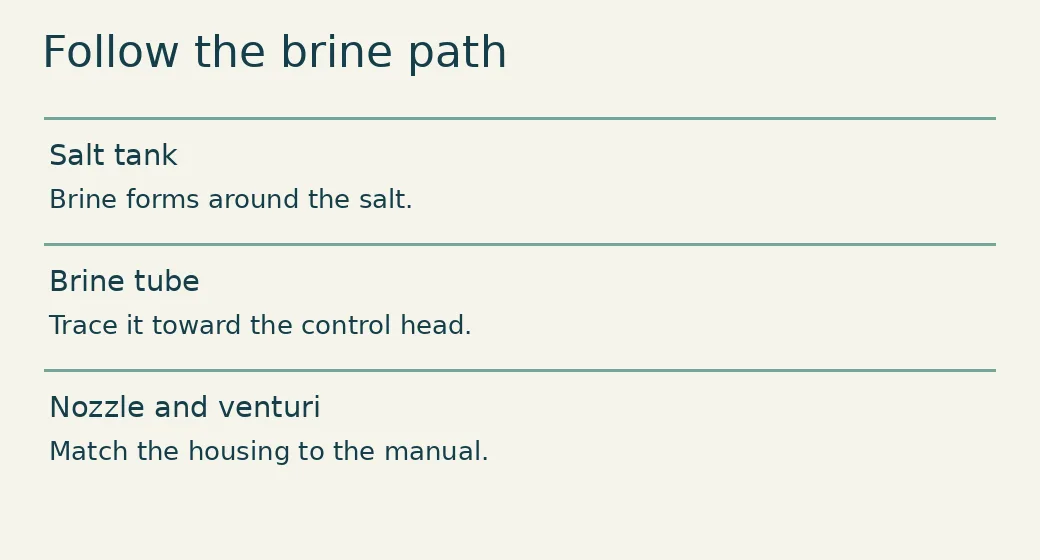
If your softener’s manual calls for cleaning the nozzle and venturi, start at the control head. On the Whirlpool cabinet models pictured in its support guide, the assembly sits on the left side of the head and has a light-colored cap over a gray housing. The narrow tube inside the salt tank is a different part: it houses the brine valve and float. Leave the cap in place while identifying the assembly.
Find the right assembly before buying a kit
- Copy the model and serial number from the appliance label. Take a photo of the control head and the connection for the small brine tube.
- Open the parts drawing for that model. Follow the small tube on the drawing from the salt tank toward the control head. Look for the labels nozzle and venturi, housing and gasket.
- Compare the cap, connection and retaining hardware with the illustration. If the shapes differ, check the valve version before ordering parts. Color alone is a poor match criterion.
During brine draw, water moving through the nozzle and venturi creates suction that draws brine from the salt tank. Debris in the passage or a damaged seal can interfere with that draw. If you are looking down into the salt tank trying to find the nozzle, the brine well identification guide shows which components live there.
When is cleaning a reasonable next step?
There are two good starting points: the maintenance interval for your model, or a troubleshooting instruction that specifically directs you to the nozzle. Whirlpool recommends annual cleaning for the units covered in its guide. If the only symptom is that the salt level looks unchanged, check whether regeneration actually ran and whether a salt bridge is present first. Use the salt consumption checks to narrow that down.
How to use the manufacturer’s cleaning instructions
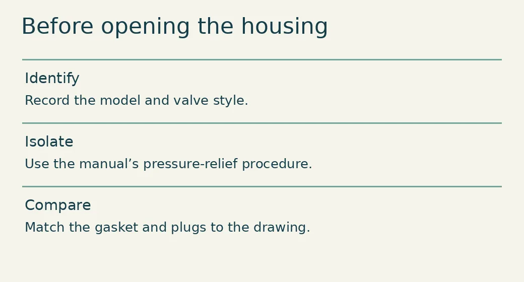
Keep the correct exploded drawing beside the unit. Follow the manufacturer’s sequence for isolation and pressure relief before loosening the cap. A bypass handle position alone does not confirm that a pressurized housing is safe to open. If you cannot confirm the specified condition, leave the housing assembled.
On the Whirlpool designs shown, the screen, nozzle, gasket and flow plugs have distinct positions. Keep parts in removal order on a clean surface and photograph their orientation. Follow the illustrated cleaning method for that version. Avoid enlarging a calibrated opening with a drill or metal pick. Reassembly depends on correct orientation and seating as well as having all the pieces.
Whirlpool’s illustrated instructions show the assembly and gasket. For a Rheem unit, use Rheem’s own cleaning guide and match the model before starting.
Clean, replace or investigate further?
For a draw problem that persists after the approved cleaning, use the injector troubleshooting guide to distinguish the next checks before replacing parts.
Visible debris with intact parts: follow the cleaning procedure. Damaged gasket, cracked housing or missing plug: identify the exact replacement in the parts list. Clean assembly but persistent poor draw: stop repeating the cleaning step and record the cycle stage, tank level and drain behavior for service.
After reassembly, restore service exactly as the manual directs, check the housing for leaks and verify operation during the specified recharge check. Record the date and what you found in your maintenance checklist.