
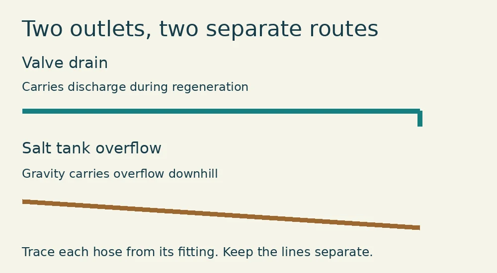
A water softener’s valve drain line carries discharge away during regeneration. Start planning at the receiving drain: find out where it empties, whether it can accept the discharge, and whether you can secure the hose above its flood-level rim. Then measure the route back to the softener. The nearest open pipe may look convenient but still leave you with too much lift or too little space for the air gap.
Which hose are you routing?
Trace the hose to its starting point. The valve drain starts at the control valve and can carry water during a normal recharge. The overflow hose starts at the elbow on the salt storage tank. On the Whirlpool WHES units illustrated in the manufacturer’s installation booklet, the overflow relies on gravity. Give it its own downhill route. Joining the two hoses with a tee can send valve discharge back toward the salt tank.
This distinction matters in a basement: an elevated laundry tub might be within the valve drain’s permitted lift but still be too high for the tank overflow. Mark the destination of each hose separately on your sketch.
Where can a water softener drain?
| Possible destination | What to establish before choosing it |
|---|---|
| Floor drain | Trace its destination, check that it accepts the discharge, and identify a way to secure the outlet above the drain while leaving the grate accessible. |
| Laundry tub | Measure to the rim, including the air gap above it. Consider what happens if someone plugs the tub or leaves laundry in it during an overnight recharge. |
| Standpipe | Have the receiving arrangement and capacity checked, especially if a washer already uses it. A hose pushed down or sealed inside a pipe loses the visible air gap. |
| Outdoor outlet, sump or septic system | Identify the final destination and ask the local wastewater authority or septic system professional whether it can receive regeneration discharge. For an outdoor run, include freezing exposure in that review. |
A garage floor grate, for example, tells you where water enters the floor. It does not tell you whether it goes to a sanitary sewer, a storm drain or outdoors. If the destination is unknown, resolve that question before buying fittings or cutting tubing.
How to measure the drain line air gap
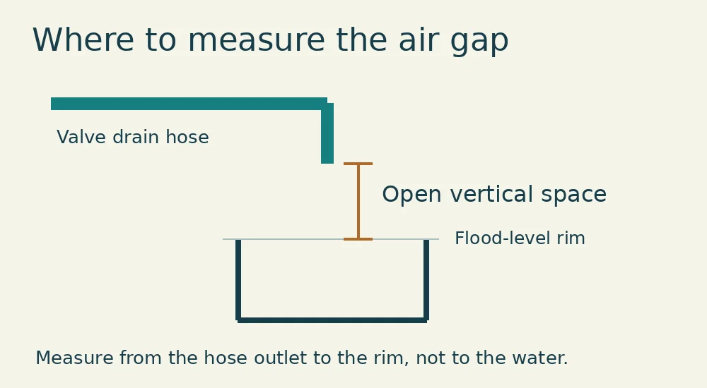
Find the level at which the receiving fixture would spill over. Measure vertically from that rim up to the lowest edge of the hose outlet. Measuring down to the bottom of an empty tub makes the separation look much larger than it really is. The open space keeps backed-up drain water from reaching the hose end.
Can the valve drain line go up, and how far can it run?
Some models allow a rise. Write down the model number first, then check the drain section in its installation manual. Record the reference point for the height measurement as well as the number. A height measured from the floor and a rise measured from the valve are different measurements.
For a concrete example, Whirlpool’s drain hose requirements specify a 3/8-inch inside diameter, a maximum height of 8 feet above the floor, a maximum horizontal distance of 30 feet, and a 1½-inch air gap. Use those figures only for equipment covered by the instructions. For a GE GXSH40V, for instance, start with the GXSH40V owner’s manual for the actual unit. Confirm the required material and local installation requirements as well.
Worked example: Suppose a Whirlpool installation covered by that guidance needs 24 feet of horizontal routing. The proposed ceiling attachment would put the hose 9 feet above the floor. The horizontal distance passes its check, but the high point exceeds the stated height. Moving the hose end lower at the far wall would leave the same high point. Look for a lower route or another approved receptor before proceeding.
If the appliance or proposed route could be exposed to freezing temperatures, include winterization planning for the softener system in the installation discussion.
A route worksheet to take to the installer
- Record the model and manual page. Copy the permitted inside diameter, material, maximum height, distance limit and required air gap. Record unknowns as questions.
- Sketch the actual path. Mark outlet, highest point, turns, supports and receiving rim. Measure along the route around cabinets and doors rather than straight across the room.
- Check both outlets. Label the valve line and overflow separately. Identify any uphill section in the gravity route and any kink or loose coil in the valve route.
- Confirm the destination. Record who verified where the receptor drains and whether it can handle the flow. If it is shared, include the other appliance in the discussion.
- Observe commissioning. During the manufacturer’s startup procedure, check whether the hose stays secured and the receptor keeps up without splashing or backing up. If discharge looks weak or the receiving drain backs up, record the cycle stage and check where the drain flow is restricted.
Once the unit is in service, use the homeowner’s maintenance checklist for routine checks. If the outlet keeps flowing after recharge ends, go to water softener draining continuously. If water is coming from the salt tank overflow, use the high brine tank water level guide and note when the level starts rising.